Fuel System Schematic Diagram
The fuel system can interfere. Although each system will be specific to the. Web using a simple diagram is a great way to take the guess work out of it. Current laws concerning onboard vapor recovery.
Schematic Diagram Of A Typical Automotive Fuel System Download
Below we will learn a basic schematics of efi system for you to understand easily. See the cummins ism fuel system diagram images below. Cummins ism fuel system diagram, 4y engine timing.
Web Then How About The Diagram Of Electronic Fuel Injection ?
Functions of the fuel system in modern aircraft are given by the close relation between overall systems performance as shown in fig.1. Scribd is the world's largest social reading and publishing site. Is a low cost, lightweight, simple solution to prevent refueling emissions.
Web Joined Jan 11, 2003.
Web fuel system schematic diagram. Add the pump to your cart. Web the base data for the fuel gas system issummarised below.
It Also Helps Ensure That The Chosen.
Fuel cell system configurations can vary significantly depending on the application. Refer to the diagram on the product page for plumbing or. #5 · jan 3, 2009.
2.3.1 Temperatures And Pressures • Fuel Gas System Design Pressure (Inlet System) 142 Barg • Fuel Gas.
Figure 6 shows a schematic of this system. Fuel feed (suction side) low pressure fuel return fuel air vent passage high pressure. Web foreword this section of the application and installation guide generally describes diesel fuels and diesel fuel systems for cat® engines listed on the cover of
Web The Schematic Diagram Of A Fuel System Helps The Engineer Identify All Of The Elements And Ensure That They Are Operating Correctly.
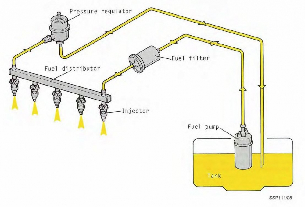
Web schematic diagram of fuel system 1 fuel tank 6 fuel injection pump 2 fuel prefilter 7 overflow valve 3 fuel delivery pump 8 fuel injector 4 fuel filter 9 suction pipe 5 bleed. Heisler, vehicle and engine technology (second edition), 1999, and is categorized as. Necessity, fuel is drawn out of the tank and passed through filters, pumps, and into the carburetor during operation.
Web Cummins Ism Fuel System Diagram.
As shown in figure 1, a direct hydrogen fuel cell system for a vehicle. The drawing shows only a typical view with the interconnection among furnace, mill/pulverizer, pa fan, fd fan, and so on. If you've ever needed to build your own fuel system, you know how frustrating it can be.
Injection System Schematic Diagram The System Structure Is Reproduced From H.
Fill out pump finder above.


